


Fritzing
I'll probably learn Eagle someday but for now all I can handle and teach my high school students is breadboarding to PCB design in Fritzing.

Some things I learned along the way through this process:
- Single side only, make sure everything is on top or bottom layer, one or the other.
- Make all traces extra thick (48 mil).
- To add jumpers, add a bendpoint on either side of the gap, delete the middle trace, and drag the orphaned traces to the jumper. Then drag the jumper where you want it. You can resize a jumper if you get the mouse in the right place, somewhere on the blue but hard to find.
- Command + click + drag to move bendpoints more precisely without snapping to grid.
- I could only get FlatCAM to cut rectangular board outlines so don't bother with non-rectangular outlines unless you can figure out how FlatCAM can do other shapes.
- Any component with more than 2 legs/pins must be moved to the other side from the traces as you are looking at the bottom of your board and any DIPs or microcontrollers or transistors or whatever will be on the other side. If you don't do this they will be backward and circuits will be wrong.
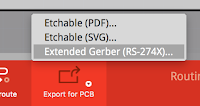
Once designed, export to Extended Gerber.

FlatCAM
With FlatCAM you take your Gerber files and create gcode instructions Carvey can use. Beware, I got FlatCAM working on my Mac with much command line hassle but wasted a class trying to get my students through it. They had too many varied problems and idiosyncratic issues to solve. It's a bunch of Python files and dependencies on Mac. On PC you can just get an installer and it just works, so that's what I ended up doing, having students work through it one-at-a-time at the PC connected to the Carvey. I owe everything to this Inventables forum post, which details the process wonderfully. But here are my modifications:

Select your copperTop.gtl file in the Project panel.
Click the Selected tab.
Scroll down to the Offset section.
Type in the value 25.4 for the x and y offset, and click the Offset button.
We have to do this to move the milling area away from the Carvey’s Smart Clamp at the lower left of the machine. 25.4 mm = 1 inch and with any smaller margin the Carvey won't accept the gcode file.


Isolation Routing
Scroll back up to the Isolation Routing section and change the Tool diameter to 0.3. Leave the rest and click Generate Geometry. We are using a 0.2 mm V shaped engraving bit for this step but a 0.3 mm diameter setting will give the traces a little more room.
Your traces will get a red border.

Go back to the Projects tab and you’ll see a new file with a .gtl_iso extension. Select that file and click Selected.
Type in the following settings:
Cut Z: -0.1
Travel Z: 1
Feed Rate: 254.0
Tool Diameter: 0.3
Click Generate.


Whew, the first of your gcode files is done!
We need a 2nd, wider pass, and then a 3rd. Go back to the Project tab, click the copperTop.gtl_iso file again, click Selected, and change the tool diameter to 0.5.
Click Generate. The blue lines will get thicker.


Click Generate. Again, the blue lines will get thicker.
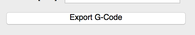
Back in Projects, click the new gtl_iso_cnc_2, click Selected, scroll down, click Export G-Code, and name this file “iso_2mmPASS3.gcode”.

Non-Copper Area
Next we create gcode for the area outside of the traces, called the "paint area."Go back to the Project panel, all the way back to the top and select the file with "copperTop.gtl" in it, and click Selected.
Scroll down to the Non-copper Areas section and set the Boundary Margin to 3.3, then click Generate Geometry.

Go back to the Project panel and select the last entry that ends with .gtl_noncopper, and click select.
Scroll down to the Paint Area section and input the following:
1.58 for the Tool diameter, which corresponds with the Carvey 1/16" flat milling bit.
0.15 for the Overlap
0.25 for the Margin

Click Generate, and you will be asked to click the area to cover, so click in an area of the board but NOT on a trace. Red toolpaths will be drawn in the non-copper areas.

Now go back to the Project panel and click the new entry with "gtl.noncopper_paint" at the end, and click Selected. Under Create CNC Job, enter the following:
Cut Z: -0.05
Travel Z: 1
Feed Rate: 230
Tool dia: 1.58
Now click Generate and you will see the red toolpaths fill in with blue.

Now back in the Project panel select the file ending in "gtl.noncopper_paint_cnc" and click Selected. Click Export G-Code down at the bottom and save the file as "paint158.gcode".
Drill Files
Go back to the Project tab. Click File > Open Excellon and select the file in your folder with “drill” in the name, and open it. You will see some red circles added to your layout.

Now your holes should line up with the traces.

1.2mm = purple
1.1mm = maroon
1.0mm = dark green
0.80mm = blue
0.90mm = goldenrod
0.70mm = yellow
0.60mm = red
0.50mm = green
0.40mm = white
0.30mm = orange
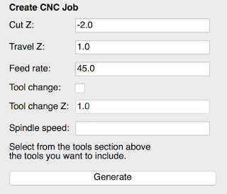
Different components in your PCB need different sized holes drilled for them, so we will be making two different gcode files, each one for a specific bit size. To simplify the job we will make one file for the 0.9mm bit, and one for the 1.0mm bit.


Cut Z: -2
Travel Z: 1
Feed rate: 45.0
And click Generate.

Click Generate.
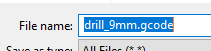
Back in the Project panel you will see a file with drill.txt_cnc_1. Select it, click Selected, and click Export G-Code.
Name this file drill_1mm.gcode
Last Gcode File! Your Board Outline
Back to the Project tab. Click File > Open Gerber, and select your file with the word contour in it. You will see a green outline added to your layout.

Now scroll up to the section in the panel Board cutout. Enter the following:
Tool dia: 1.58
Margin: 0.1
Gap size: 0.5
Gaps: (leave 4 selected)

Click Generate Geometry. Now a red line will appear.

CutZ: -2
Travel Z: 1
Feed rate: 60.0
Tool dia: 1.58
Click Generate.
FYI: 1.58 mm = 1/16 inch. You will use a 1/16 inch flat end milling bit to cut the board out of the blank, leaving 4 tabs around the sides to hold it in place.

Carvey Time!
Go to easel.inventables.com and create an account.
Click New Project, then File > Import gcode, and select your PASS1.gcode file and see if it will import properly. Here is what mine looks like:


No comments :
Post a Comment